
In the aerospace industry, CubeSats have emerged as a low-cost, easily manufacturable solution for space-based optical systems. They offer a unique opportunity to develop a production line approach for a space-based products through constellations of smaller, more affordable systems.
Companies that manufacture CubeSat optical systems need an accurate and reliable method for developing an optical design, opto-mechanically packaging the system, and modeling structural and thermal impacts that the system will experience in orbit. This article will explain the high-level development of a CubeSat system by using the Ansys software suites. We will illustrate how an integrated software toolset can streamline the design and analysis workflow.
For decades, optical systems have been developed for operation in low, medium, and high Earth orbit. For many optical systems, the packaging form factor and the opto-mechanics that stemmed from this form factor were designed on a system-by-system basis. CubeSats are a class of lightweight nanosatellite that can house optical systems for applications ranging from laser communications to Earth imaging. They are unique in that they use a standardized size and form factor.
The CubeSat form factor is based on a standard that was originally developed as a collaboration effort between California Polytechnic State University and Stanford University’s Space Systems Development Laboratory (SSDL).2
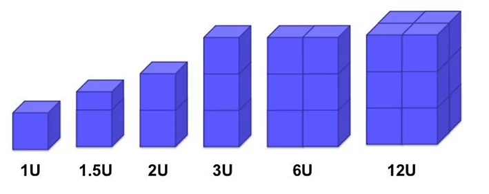
The building blocks for standard CubeSat systems are in 1U — or one unit — cubes that measure 10 by 10 by 10 centimeters. While a 1U CubeSat is the base size, CubeSats can be built to a larger form factor through the addition of more 1U building blocks. The following graphic from NASA provides an illustration of standardized CubeSat sizes.3
he CubeSat optical design referenced in this article series is an off-axis segmented, reflective telescope of the Ritchy-Chretian type. The design is meant to fit into a standardized 3U CubeSat form factor, or 10 by 10 by 30 centimeters. To maximize the field of view, the design consists of two hyperbolic mirrors that are rectangular in shape. The primary mirror and secondary mirrors have dimensions of 80 by 80 millimeters and 41 by 24 millimeters, respectively.
This design is meant to function as a high-resolution Earth imager in low Earth orbit (LEO) at 700 kilometers. The design has an effective focal length of 685 millimeters and is designed to work in the visible spectrum. At the primary wavelength, the design has a ground resolving distance of 9.11 millimeters which enables system engineers to image two distinct objects that are at least that distance apart. The ground resolving distance can be calculated with the following equation:

As designed in OpticStudio, the CubeSat is assumed to operate at room temperature, but in orbit, the optics are expected to perform at an operating temperature of 15 degrees Celsius, plus or minus 3 degrees. The detector for this system has an active array of 1280 by 800 pixels, with each pixel being 3 by 3 micrometers (μm). This allows for a total imaging area of 3.84 by 2.4 millimeters.
The main performance metrics for this design are to achieve a diffraction limited spot size at every field point and to achieve a modulation transfer function (MTF) of 0.25 at 80 cycles per millimeter. These metrics were referenced from the same paper on which this design was based.
Based off the design prescription, global system parameters were set in the System Explorer, and the optics were inserted with the proper specifications in the lens data editor.
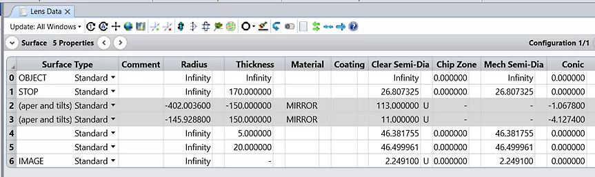
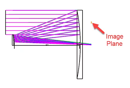
Even though the final design contains mirrors with rectangular apertures, the first stage of the design had the mirrors retain a circular shape. Retaining the circular shape of the mirrors prevents the optimization from being over constrained at the start of the process. To position both mirrors off-axis, the two mirrors were decentered with respect to the global optical axis. Because of this, even though the rays are able to focus on the correct location, the image plane is offset from the rays. At this stage, the image plane is floating near the top of the primary mirror and is aligned with the global optical axis of the coordinate system.
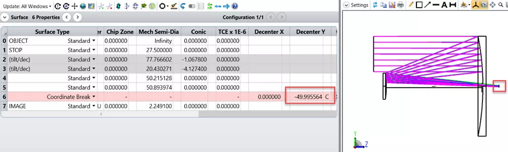
To be brought to the correct location, the image plane needs to be decentered with a coordinate break. Using a chief ray solve on the Decenter Y measurement, the image surface is aligned with the real chief ray. The image plane is now properly positioned.
With the basic layout finalized, optimization can now begin. To preserve the system’s F/# of 12.455, an effective focal length (EFFL) operand was used in the merit function to target 685 millimeter in conjunction with a root mean square (RMS) spot size default merit function. Multiple optimization runs were conducted in which the radii of each surface and the thicknesses were iteratively optimized.
Because space is limited in a CubeSat system, it is critical to pay close attention to the total track length of the system and areas in which to vignette the rays. The total track length for this design is 19.5 centimeters with 2Us of space devoted to the optics. The remaining 1U of space is devoted to system electronics. The total track length can be monitored via the merit function by using a thickness (TTHI) operand between the STOP and the image plane.
After verifying the design would fit within the size constraints of a 3U CubeSat and ensuring that performance was as expected after optimization, the mirrors were adjusted to be rectangular. They were adjusted to the proper shape by applying rectangular apertures.
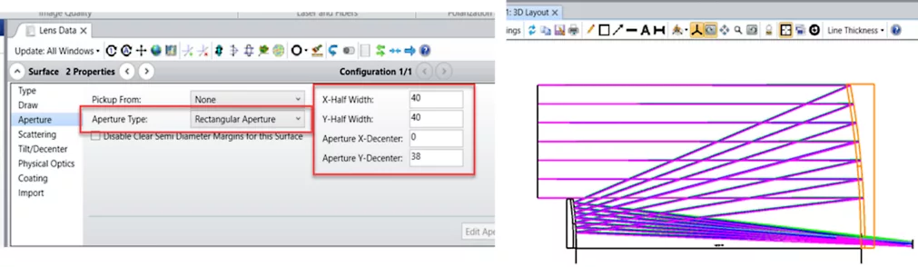
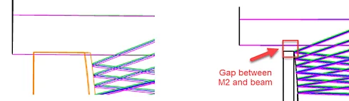
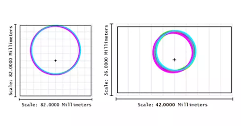
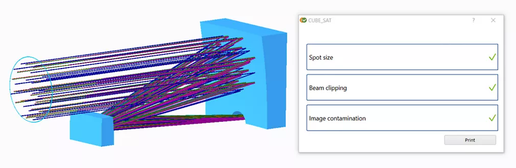
After adjusting the aperture settings, it was discovered that the secondary mirror was partially clipping the incoming ray bundle. With further decentering of the secondary mirror aperture, the results were favorable. After adjustment, the footprint diagram was used to verify that the full beam footprint reaches every critical surface of the system.
At this stage, the design has been laid out in OpticStudio, optimized, and adjusted such that it fits within a 3U CubeSat form factor.
The spot size is diffraction limited at all field points, and the MTF meets the specification of 0.25 at 80 cycles per millimeter. With the optical performance meeting requirements, the mirror thicknesses were increased as a final update to the base model. If the mirrors remain as thin as 5 millimeters, this could cause issues down the road when applying a temperature condition across the optics. In the Draw tab of the Object Properties menu, the thickness was adjusted to 18 millimeters and 15 millimeters for the primary and secondary mirrors, respectively.
After designing an optical system, the payload’s opto-mechanics can be modeled. With Ansys Zemax OpticsBuilder in Creo Parametric, exporting an optical model to a computer-aided design (CAD) environment is streamlined and intuitive. OpticsBuilder brings an optical model into Creo by generating native geometry for each optical component. With OpticsBuilder, optical simulations can also be run directly within Creo, limiting the need to transfer an optical system between optical design and CAD software. This allows for increased engineering efficiency.
With the optical design completed, opto-mechanics need to be designed to retain the optics to suitable tolerances. To easily build opto-mechanics into our system, the optical design can be exported from Ansys OpticStudio to a CAD environment via OpticsBuilder.
To export the optical design, use the Prepare for OpticsBuilder tool in OpticStudio. When exported, OpticStudio packages all relevant information into a .ZBD file and automates a few tasks for you.
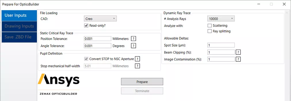
This tool confirms that all surfaces and objects in the optical design are compatible with Creo before running a ray trace to analyze system performance. The results of this ray trace are used as a point of comparison once the .ZBD file is imported into OpticsBuilder. When the file is imported into OpticsBuilder within Creo, a second simulation is performed by dynamically running a new ray trace. This ray trace verifies that the system performance of the imported optical system has not changed.
Next, the external CubeSat frame and opto-mechanics need to be designed. There are several considerations to be made during this section of the design process, including:
OpticsBuilder’s simulation tool set and capacity for importing optics into CAD as native geometry allows for a streamlined opto-mechanical design workflow. Eliminating the need to continuously transfer a design between optical design software and CAD for specific tasks allows for tackling these design challenges with increased efficiency.
For this CubeSat workflow example, the opto-mechanics were designed to a standard CubeSat form factor of 3 Units (U). 1 U of space is equivalent to 10 by 10 by 10 centimeters. The CubeSat standard was created by Stanford University’s Space Systems Development Lab and California Polytechnic State University, San Luis Obispo. More information on the developed standard can be found here.
First, the external frame of the 3-U CubeSat was sketched in Creo Parametric. The following picture displays the external frame without any optics present.
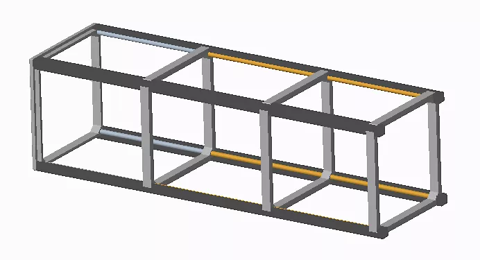
With the external frame developed, the optical design was housed within the structure. Opto-mechanics were then built to retain the optics and mate them to the external frame.
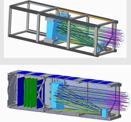
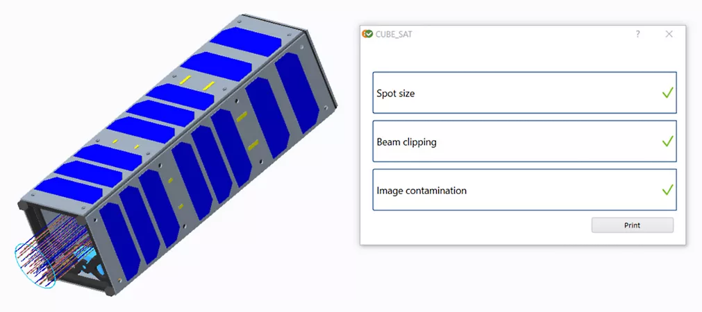
With the opto-mechanical design finalized, the impact of these components on optical performance can be simulated within Creo Parametric with the Simulation tool. For the final simulation, the full opto-mechanical model was encased with solar panel shielding.
The ray trace simulation verified that the opto-mechanics did not have a significant impact on optical performance. The fully built system can now be exported to finite element analysis (FEA) software to begin STOP analysis.
With OpticsBuilder, the gap has been bridged between optical engineering and mechanical engineering. With a streamlined and intuitive workflow, engineering teams can be more efficient in tackling the challenges of opto-mechanical design.
For an opto-mechanical payload, it is important to consider the structural and thermal impacts that it will experience in-orbit. With Ansys Mechanical, a finite element analysis (FEA) can be performed to analyze these effects. To prepare for FEA, Mechanical can be used to mesh the opto-mechanical model and define boundary conditions for the analysis. Once an FEA is completed, the Export to STAR extension within Mechanical provides a streamlined process for preparing the data for use with the Ansys OpticStudio STAR module.
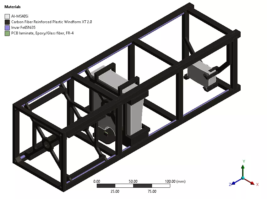
The completed design was exported as a STEP file. Within Mechanical, the STEP file was opened and prepared for FEA. For the purposes of this example, the following material definitions were chosen for the design:
-Both mirrors are built out of a low-CTE aluminum substrate (Al-MS40Si)2.
-The main frame is built from carbon fiber-reinforced polymers.
-The metering rods are built out of invar.
-The image sensor is assumed to be made from printed circuit board (PCB) laminate.
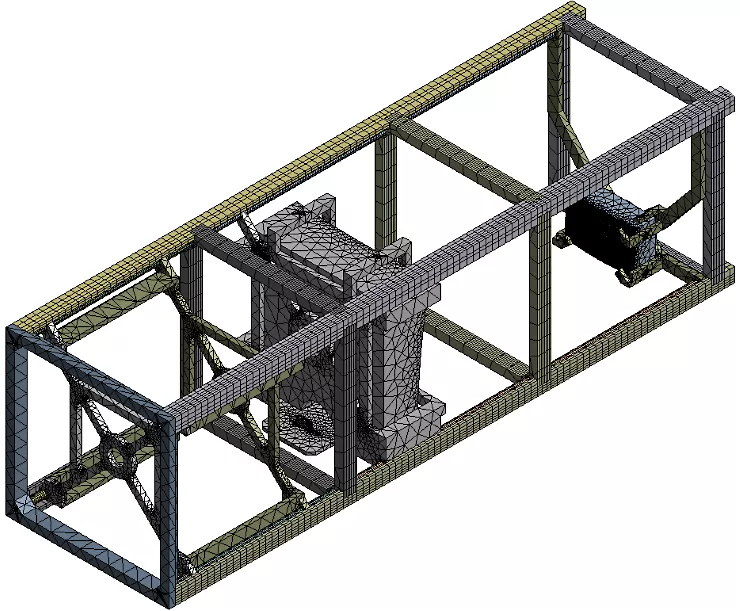
After assigning materials to the model, it was then meshed. A mesh is made of elements that contain nodes representing the shape of the geometry. For the mesh, it is important to note that the element size was adjusted for both mirror surfaces such that they each contained at least 10,000 nodes. A high number of nodes ensures good fit quality once FEA data is brought into the OpticStudio STAR module for future analysis. The following image shows the final mesh that was used for the opto-mechanical model.
For the purposes of this example, the only load considered was a thermal condition that caused all components to expand according to their thermal coefficient of expansion (CTE). It was assumed the CubeSat’s radiation control system would insulate the optics from large fluctuations in temperature. Discrete temperatures of 12 °C, 15 °C, and 18 °C were chosen to represent the operational temperature range experienced by the CubeSat in low Earth orbit (LEO).
The nominal design as built in OpticStudio was assumed to have been built in an ambient, room temperature environment of 21 °C. This is the reference temperature at which the geometry was defined.
The temperatures as implemented in Mechanical were as follows:
With the opto-mechanical model meshed and the thermal loading determined, an FEA was then conducted within Mechanical. The following image showcases the structural deformation impact for the lowest operational temperature (12 °C).
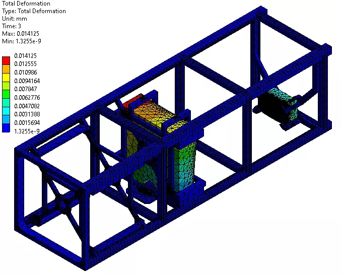
Because this payload consists of two mirrors, only structural deformation data was solved for. Solving for thermal index changes throughout an optic would be necessary if any refractive components were integrated into the system. Both structural deformation data and thermal index data can be exported to the OpticStudio STAR Module for analyzing their impact on system-level performance.
With the FEA completed, the next step is to bring the structural deformation data for both mirrors into the OpticStudio STAR Module. With the Mechanical Export to STAR ACT extension, the structural deformation data can be easily exported into the text file format utilized by STAR.


Thank you for your message. It has been sent.
Please Check Your Email